Page 56 - RSE - Results of the Apollon Project
P. 56
Results of the APolloN PRoject ANd coNceNtRAtiNg PhotovoltAic PeRsPective
required in order to synchronize the system every 1 second. Time is a critical FiguRE 61. Tracker Control
parameter in the control system, in fact, a delay of 10 seconds in the clock board developed by TECNALIA
of the control system could mean errors greater than a 0.1 deg. Probably
the most interesting function of the control board is the implementation of
a web server on the microcontroller. This way the system can be remotely
managed, confgured and read. Nevertheless, manual control of the system
is also possible by means of a joystick. The dimensions of the control board
developed are reduced in order to be able to enclose it in a small box making
the control device more attractive for the market. The control board has been
assembled in a box next to a power supply and two batteries. The power
supply can provide energy to the electronic board and charge the batteries. In
case of power cut lasting for a period of time that exceeds that set by the user,
the power supply will provide the control board with the energy stored in the
batteries in order to move the system to a secure position.
Actuators, Electric Motors
The control system is composed of two independent boards: one is in
charge of providing communications to the system and carrying out the tracking algorithm while the other is only
in charge of controlling the motors. This way, if the motor is changed in the application (change in weight, structure),
only one control board has to be changed, providing the system with better confgurability. In fact, different motor
controllers have been used including self-developed and commercial ones, depending on the tracker tested.
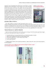
tracker Structure for Apollon Modules
Figure 62 shows the APOLLON tracker system with a panel consisting of 5 APOLLON modules (quantity envisaged
in the project; total 160 cells). The tracker is composed of:
p foundation with micro screw bars (potential low-cost solution depending on terrain);
p main column, polygonal and conical (see details further below);
p TGB Rotation Device DAD-8-659 (see details further below);
p Tacker Control (Tecnalia);
p torsion tubes and frame.
A slightly different version of this tracker was installed in Gorizia, Italy in the course of the APOLLON project,
see next paragraph.
FiguRE 62. Apollon tracker confguration with a panel consisting of 5 Apollon modules
with 32 receivers each (source: ASSE s.r.l.)
55