Page 15 - RSE - Results of the Apollon Project
P. 15
Results of the APolloN PRoject ANd coNceNtRAtiNg PhotovoltAic PeRsPective
the Problem of group iv and group iii-v Semiconductor growth incompatibility
InGaP/InGaAs/Ge TJ structures are generally built with only the top and the middle junctions grown epitaxially,
while the third junction is formed by atom diffusion into the germanium substrates. This realisation process is
detrimental to the third junction, since the dopant profles in the junction are not abrupt and high surface
recombination velocity can be encountered at the interface between Ge and the frst nucleation layer, which reduces
the open circuit voltage (Voc) and the short circuit current (Isc) of the bottom Ge cell. Other interesting solutions
, as reported in the last chapter of this book on the utilization of group IV and III-V alloys for high effciency solar
cell, support the motivation to investigate new routes for reducing the incompatibility between group IV and III-V
elements. So far, the possibility to grow Germanium and its alloy in the same MOCVD growth chamber to be used for
the subsequent III-V MJ growth has been hindered by the “carry over effect”: since Ge is a dopant for III-V compounds,
after epitaxial Ge deposition, Ge can continuously evaporate from the MOCVD reactor walls and susceptor limiting
the formation of the N/P junction in the subsequent growth of III-V layers.
The same detrimental effect can be expected in the subsequent growth of the Ge-junction in the next growth run
as III-V-atoms then covering the reactor surfaces also act as dopants in group-IV semiconductors. In addition, the
growth conditions for the growth of Ge and GaAs can be quite different in terms of growth pressure and temperature.
In order to face the challenge of Ge desorption from the reactor walls and remove the growth incompatibility of Group
IV and group III-V semiconductors, a new design of the MOCVD reactor growth chamber was needed.
APOLLON Progress with Respect to State-of-the-Art MOCVD
temperature tuning Capability
The requirement of removing the supposition of semiconductor wafers under strain-free conditions resulted
in a paradigm change in MOCVD equipment design, since the changing thermal gradient induced by the loss of
mechanical contact between wafer and graphite had to be compensated in-situ, i.e. during growth, by adjusting the
center-to-edge temperature of the wafer carrier to keep the wafer surface temperature constant and uniform. The
basis for development was provided by the RSE specifcations that AIXTRON applied to the AIX 2800G4 Planetary
Reactor platform which features a main RF-heated susceptor carrying 12 four-inch wafer carriers. Those wafer
carriers, called “satellites”, are rotated on a gas-foil.
Several approaches to infuence the thermal gradient across these satellites were investigated. They ranged from
mechanically adjusting the RF-coil heights via RF-feld displacement to using the gas foil (GFR=Gas Foil Rotation)
itself for temperature control. Numerical CFD (Computational Fluid Dynamics) simulations yielded the best results
and maximal satellite temperature profle tuning capabilities for the GFR approach. Different inert gases, such as H
2
or N , have quite different thermal transport coeffcients, implying that by administering H , N or a mixture thereof
2 2 2
to the center and edge of the satellite gas foil separately, the thermal transport from the homogenously heated
susceptor to the satellite can be modifed. Thus, by injecting H (with a high thermal transport coeffcient) at the
2
center and N at the edge, the center of the satellite can be tuned hotter and the edge colder (concave temperature
2
profle, see Figue 4 left). In turn, by injecting N at the center and H at the edge, the effect can be inverted (convex
2 2
temperature profle, see Figure 4 right). Analogously any mixtures of H and N in between can be used to adjust any
2 2
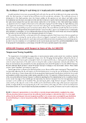
FiguRE 4. Schematic representation of a dual GFR for a convexly shaped wafer (left) H 2 is applied at the center
GFR area, boosting thermal transport from the uniformly heated susceptor to the satellite, while N 2 at the edges
reduces the thermal transport (concave temperature profle). In the concave wafer case (right) the gas distribution
is reversed leading to a convex temperature profle. All intermediate stages can also be reached by using H 2 /N 2
mixtures
Bowed Wafer
Satellite
2-fold inner
& Outer gas Foil
Susceptor
hEAt SOuRCE uniform hEAt SOuRCE
heat Source
14