Page 44 - RSE - Results of the Apollon Project
P. 44
Results of the APolloN PRoject ANd coNceNtRAtiNg PhotovoltAic PeRsPective
The aluminium-polyimide system is an adhesiveless foil dielectric. For reducing the deformations caused by cyclic
changes of temperature, the aluminium foil is welded through holes to the back of the cells and assembled with
thermally compensated loops. A receiver without SOEs is shown in Figure 47.
FiguRE 47. COF-receiver without SOEs
Flexible aluminium-polymide boards
Heat sink
Solar cell
9 pcs.
Fragment of receiver
in the area of cell bonding
To avoid the negative infuence of assembling processes on the solar cell photovoltaic parameters, an ultrasonic
bonding operation of fat fexible boards and carriers, which are made from foiled dielectric to the contact pads
of solar cells, was routinely applied. Bond joints pull-strength investigations were performed by means of the
destruction of joint on tearing off and measuring pull-strength value with a grammometer. During investigations
optimal values of the main bond parameters were defned. With optimal bond parameters, pull-strength of the
bond joints was not less than 25-30 g. A typical bond joint of fat lead of fexible board to solar cell for such type of
assembly is shown in Figure 48 (profle of bond joints is obtained by Scanning White Light Interferometer)
FiguRE 48. Photo and profle of the typical bond joint of fat lead of fexible board
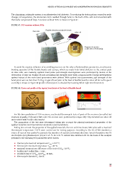
For life-time prediction of COF-receivers, accelerated thermocycle tests of parts of the receivers (so-called test
structures of quality, TSQ) and of full scale COF-receiver were performed (see Figure 49). TSQs included one solar cell
and receiver with 9 solar cells bonded.
The parameters of the test were determined taking into account the physical-mechanical properties of the
applied materials and international standards recommendations.
Taking into account the properties of the applied materials, the cost and time issues, 500 cycles with a maximal
thermocycle temperature 110 C were carried out for testing purposes. According to the IEC 62108 standard, a
.
0
source of current was applied to generate the impulses of currents in forward direction. Speed of impulses was 10
electrocycles (EC) /thermocycle (TC) at T>25 C. At T<25 C current was switched off. On the basis of the analysis
0
0
performed, the following test parameters were chosen:
p thermocycle maximal temperature T : +110 °C;
max
p thermocycle minimal temperature T : -40 °C;
min
0
p maximal temperatures difference at the tests of ΔT : 150 C;
tst
p heating and cooling time: 5 min.;
p retention time tr at T and T : 10 min.;
max min
p thermocycle duration t : 30min.
c
43